

Introduction: Why Compare Scan to CAD vs Manual Tracing?
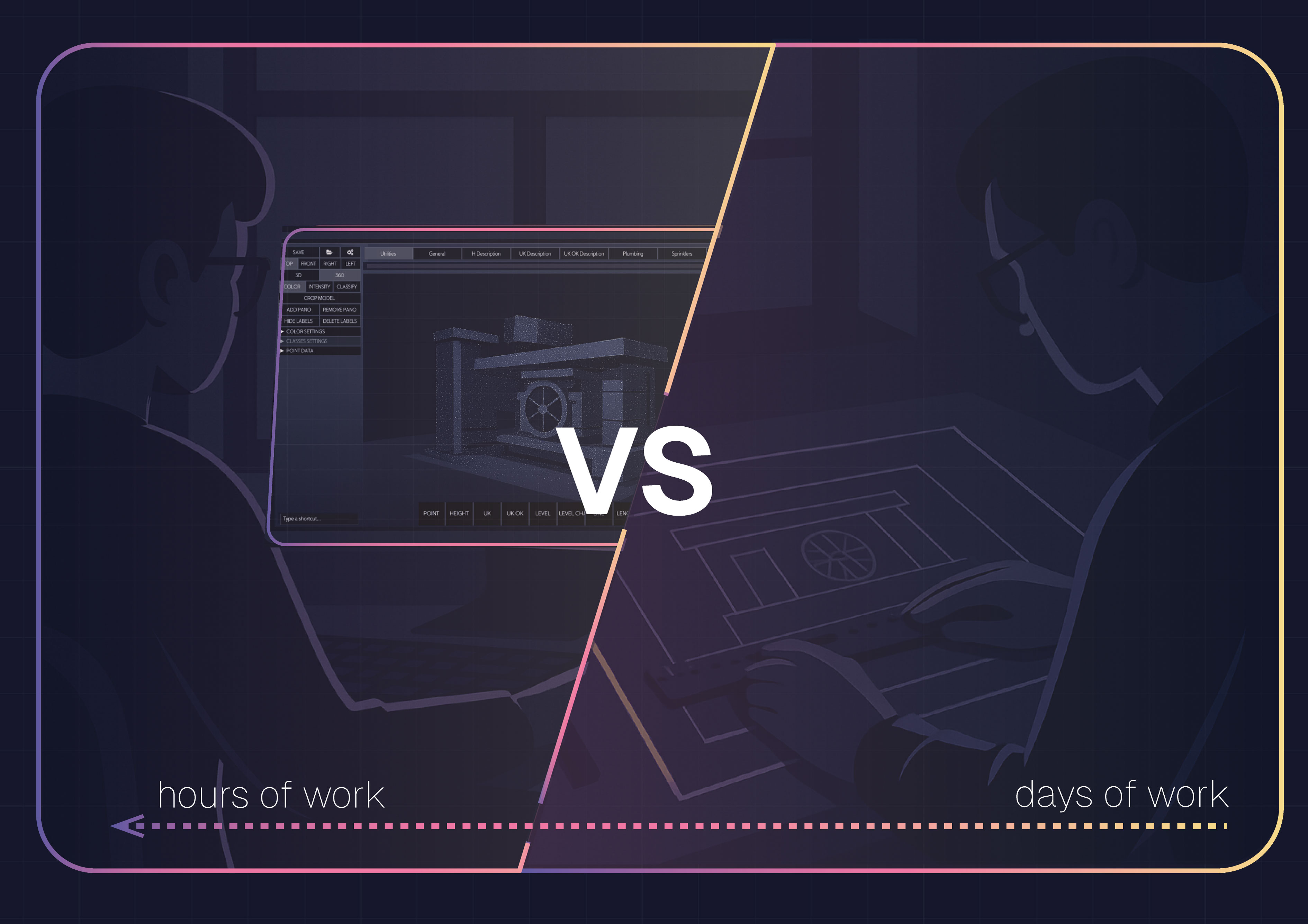
Manual tracing of point clouds has been the default in many survey and drafting offices for years. You load a massive scan, slice dozens of planes, trace walls and openings by hand, and repeat the process room by room. The result is accurate, but the workflow consumes hours of senior drafter time and pushes project budgets higher.
This is why the question of scan to CAD vs manual tracing matters. Modern software introduces automation, letting teams extract features directly from scan imagery and stream linework into CAD without redrawing everything from scratch. For surveyors, architects, and engineers, the difference is not just convenience but measurable time and cost savings.
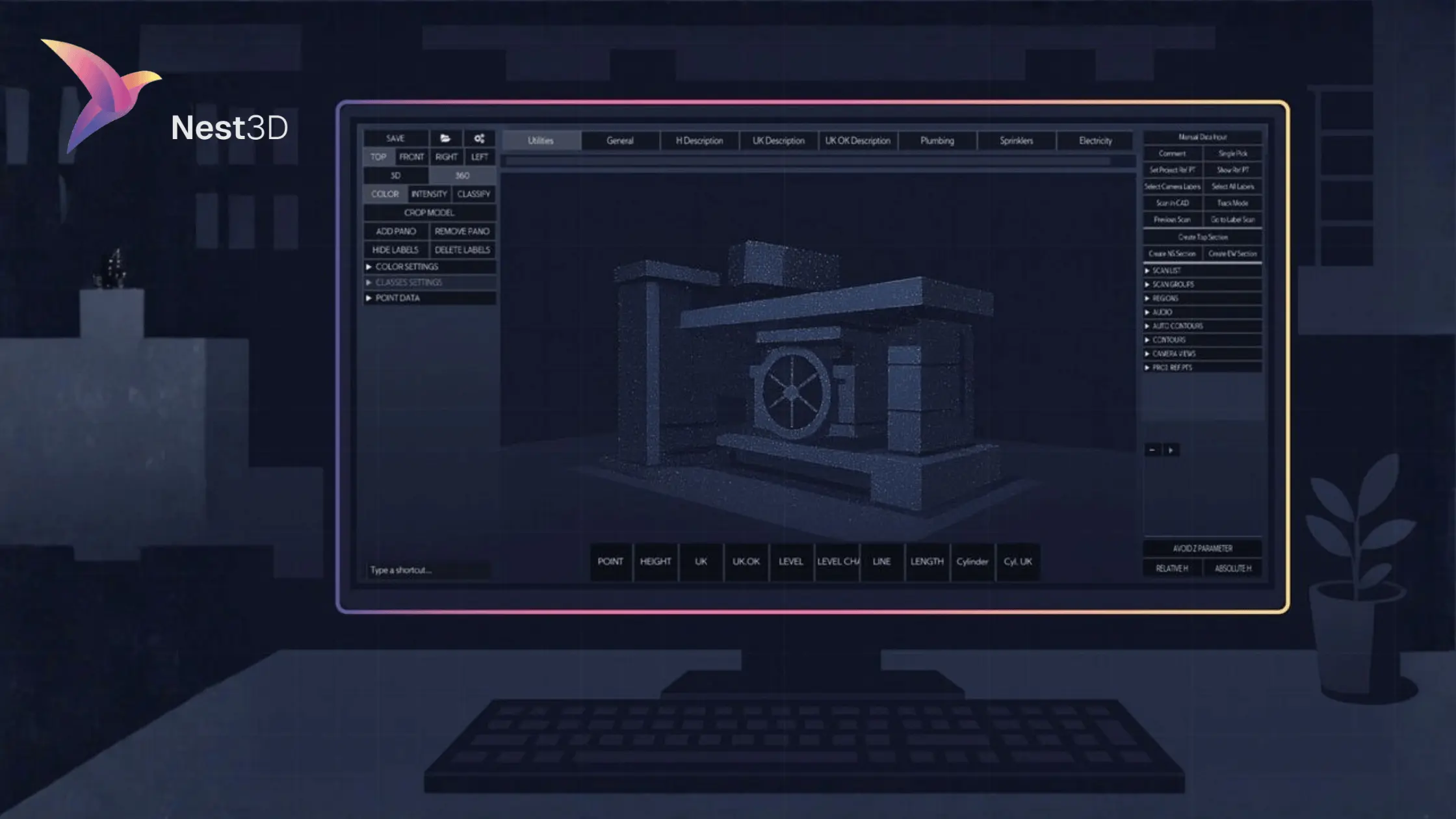
In this guide, we will outline every manual step, show exactly where the hours disappear, and prove how Nest3D lets you click features in a 3D panorama and stream DWG linework directly into AutoCAD, BricsCAD, or ZWCAD.
If you are new to this topic, start with our full guide on scan to CAD software before diving into the detailed comparison below.
What Manual Scan to CAD Tracing Involves
Before automated tools became available, most teams relied on manual scan to CAD tracing to turn point clouds into usable drawings. The process works, but it is repetitive and resource-heavy.
A typical manual CAD conversion workflow looks like this:
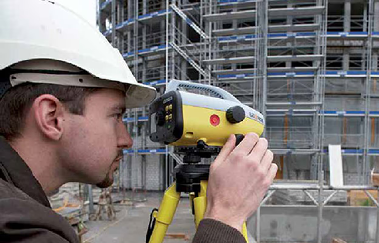
- Capture the site with a terrestrial scanner or mobile SLAM device and export a unified point cloud.
- Import or attach that cloud into CAD using an RCP file or raster panorama.
- Establish coordinates, scale, and a working UCS before drafting begins.
- Slice or section views until walls, doors, or features are visible.
- Trace linework by hand, snapping to noisy points, fitting arcs and cylinders, and placing text and blocks manually.
- Hunt for missing geometry during quality checks, often finding errors late in the process.
- Repeat these steps for every room, floor, or site area until the drawings are complete.
This workflow can deliver accurate results, but the cost is high. Every slice and redraw adds minutes, and every room multiplies the effort. The next section looks at why this traditional method consumes so much time and budget.
Why Manual Tracing Burns Time and Budget
Manual CAD conversion is accurate, but it comes with hidden costs. Each step in the manual scan to CAD workflow adds friction, and those delays multiply across large projects.
The most common problems include:
- One-plane views: Every slice or section costs minutes and requires constant adjustments.
- Visual clutter: Dense, noisy point clouds make it hard to see edges, and mis-picks often trigger redraws.
- Repetition: Symbols, blocks, and layers are copied and placed room by room with little efficiency gain.
- Skill bottleneck: Only senior drafters have the confidence to navigate noisy data, which limits scalability.
- Error loops: Missed geometry is often discovered late during QA, forcing costly rework.
For small areas, these issues might not seem significant. But when multiplied across dozens of rooms, floors, or sites, the hours add up fast. Over time, manual scan to CAD tracing becomes a profit risk, consuming senior drafter capacity and reducing project margins.
Automated CAD Conversion: How Scan to CAD Software Works
Instead of spending hours slicing and tracing point clouds by hand, modern scan to CAD software uses automation to convert scans into DWG drawings quickly and consistently. This process is often called automated CAD conversion or automatic CAD conversion from scans, and it reduces drafting overhead significantly.
The workflow is simple:
- Load your scan: Import E57 or FLS data directly into your CAD environment.
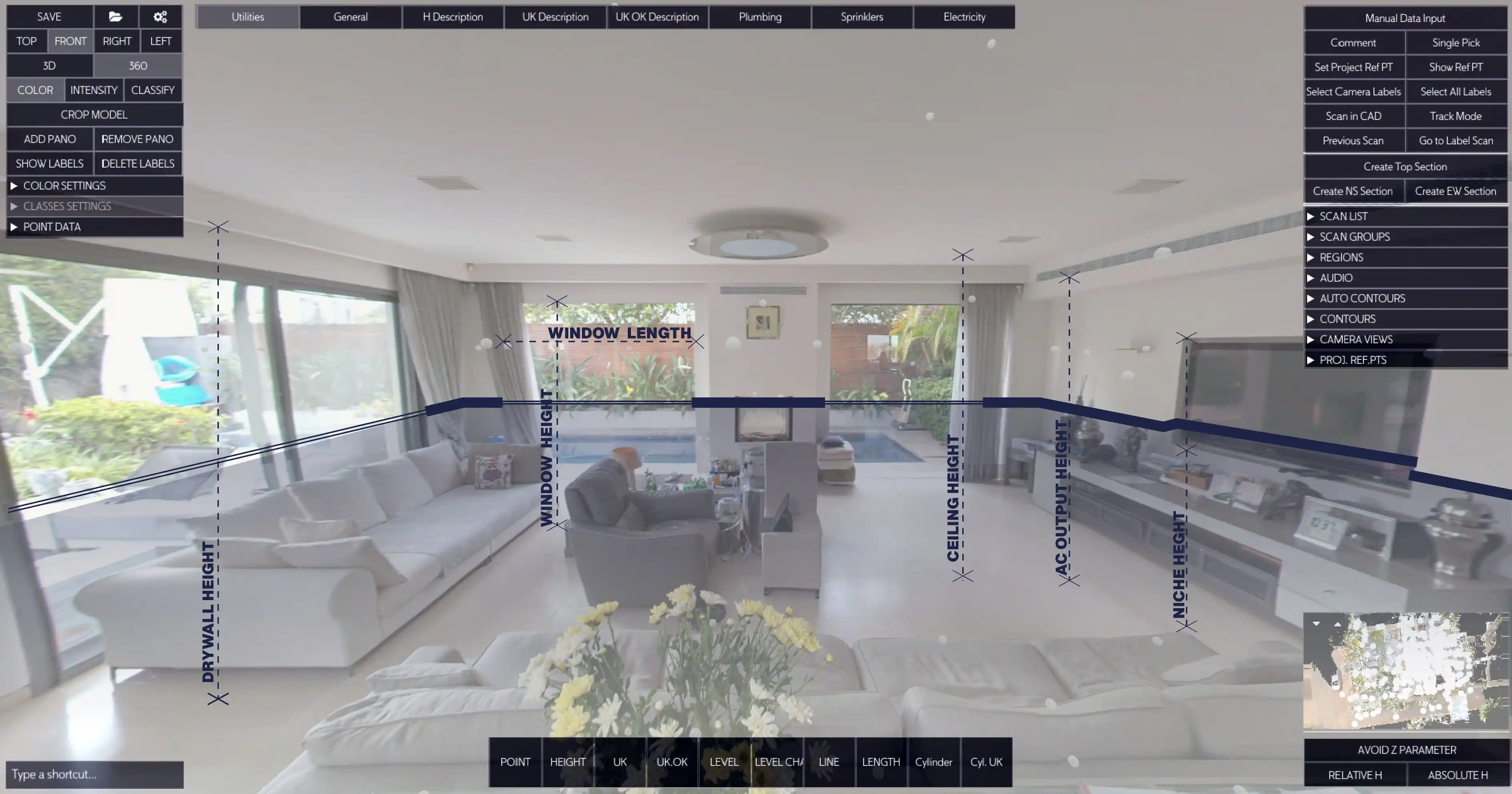
- One-click extractions: Select features such as walls, openings, heights, or cylinders directly from the scan imagery.
- See your CAD drawing take shape: Geometry is placed instantly in DWG on the correct layers with your blocks, linetypes, and colors applied.
With this approach, junior staff can handle most of the work while senior staff focus on review and quality assurance. The result is a faster, more scalable workflow that saves both time and budget.
Side-by-Side Comparison: Manual vs Scan to CAD Workflow
The difference between manual scan to CAD tracing and automated CAD conversion is clear once you compare the two approaches side by side.
Manual workflows depend on senior expertise, introduce inconsistencies, and take hours to complete. Automated tools streamline the process, improve consistency, and deliver drawings about 60 percent faster on average.
Benchmark Results: Real Project Data
Accuracy and Quality in Automated CAD Conversion
A common question is whether automated tools are as accurate as manual tracing. The answer is yes. Automated CAD conversion takes geometry directly from registered point clouds, so the detail captured in the scan is preserved in the DWG drawing.
High-resolution laser scans already capture millimeter-level precision. When those scans are properly aligned, the extracted features match real-world measurements with confidence. Manual tracing can introduce errors through mis-picks, fatigue, or inconsistency between drafters. Automation reduces those risks by applying the same rules every time.
Quality checks are still important, but the focus shifts. Instead of redrawing geometry by hand, teams spend their time verifying that the automated output meets project requirements. The result is faster drafting without sacrificing accuracy.
When Manual Still Makes Sense
Modern scan to CAD software is accurate enough for nearly every project, from floor plans to elevations and site surveys. Automation handles the majority of extractions quickly and reliably, reducing the need for manual work.
There are still situations where a manual step can add value. Extremely noisy scans, incomplete capture data, or projects with very fine ornamental details may require a drafter’s judgment. In these cases, automation provides the baseline geometry and manual tracing fills in the rare gaps.
Rather than competing with each other, automation and manual tracing can work together. Automation delivers speed and consistency, while manual input ensures edge cases are handled with the right level of care.
Scan to CAD Software vs Outsourced Services
Many teams that rely on scan to CAD conversion consider outsourcing when internal capacity is limited. Service providers can deliver DWG drawings or 3D models on demand, but this approach comes with recurring costs, longer turnaround times, and the risk of inconsistent drawing styles across projects.
Using software in-house gives teams more control. Scans can be converted on the same day they are captured, drawings stay aligned with office standards, and costs remain predictable. Instead of paying per project, software subscriptions allow firms to scale their output without sacrificing accuracy or speed.
For occasional or very specialized projects, outsourcing may still have a place. For everyday survey and drafting work, however, scan to CAD software provides better efficiency and long-term return on investment.
Run Your Own Side-by-Side Test
The best way to see the difference between manual tracing and automated conversion is to test it on your own data. Take a recent E57 or FLS scan, record how long the manual workflow takes, then repeat the same scope with scan to CAD software.
Most teams find that the automated workflow cuts drafting time by around 60 percent on average while producing drawings that are consistent with their office standards. Faster capture-to-DWG cycles mean accurate as-builts are ready sooner, which is one of the main reasons contractors and surveyors adopt point cloud technology in the first place.
Frequently Asked Questions
Conclusion: Scan to CAD vs Manual Tracing
Manual tracing has been the traditional way to convert point clouds into CAD drawings, but it is slow, costly, and heavily dependent on senior drafters. Modern scan to CAD software changes the equation by automating the process, delivering results about 60 percent faster on average while maintaining accuracy and consistency.
For most teams, the choice between scan to CAD vs manual tracing is clear. Automation reduces the hours spent on repetitive tasks, keeps drawings aligned with office standards, and delivers measurable ROI from the very first project.
Turn Point Clouds into CAD in Seconds
Cut drafting time by 60 percent and deliver accurate DWG drawings without manual tracing. Try Nest3D free for 14 days with no credit card required.
Get Started for Free
.svg)


.svg)
