

Introduction: How Scan to CAD Works in Practice
Understanding how scan to CAD works is essential if you handle laser scans, point clouds, or as-built documentation. Traditional manual tracing often eats up hours of drafting time, leaving teams over budget and behind schedule. A structured scan to CAD workflow changes that by turning raw scan data into usable CAD deliverables in a repeatable and efficient way.
If you are new to the topic, start with our Scan to CAD Software guide for a high level overview. This article focuses on the step by step workflow so you can see exactly how the process works in practice.
We will cover how to prepare your scan data, align coordinates, set up your CAD template, and follow a ten step process that converts E57 or FLS scans into clean DWG drawings. By the end, you will see how a well designed workflow saves time, improves accuracy, and allows junior staff to contribute while senior drafters focus on quality assurance.
What is a Scan to CAD Workflow?
A scan to CAD workflow is the process of converting laser scans into accurate CAD drawings. Instead of redrawing everything by hand, the workflow uses scan data such as E57 or FLS files to extract features and place them directly inside CAD platforms like AutoCAD, BricsCAD, or ZWCAD.
The purpose of a scan to CAD workflow is to produce reliable DWG deliverables such as floor plans, elevations, and sections when legacy drawings are missing, outdated, or incomplete. It ensures that surveyors, architects, and contractors can work with accurate geometry without wasting time on manual tracing.
By following a structured workflow, teams get repeatable results, reduce drafting errors, and shorten delivery times. This is why knowing how scan to CAD works is now considered an essential skill in modern survey and AEC projects.
Preparing Your Scan Data
Every successful scan to CAD workflow starts with good data preparation. If the scan is incomplete or misaligned, the problems will carry into your CAD drawing and cost extra time later. Focusing on capture quality and organization makes the conversion process smoother.
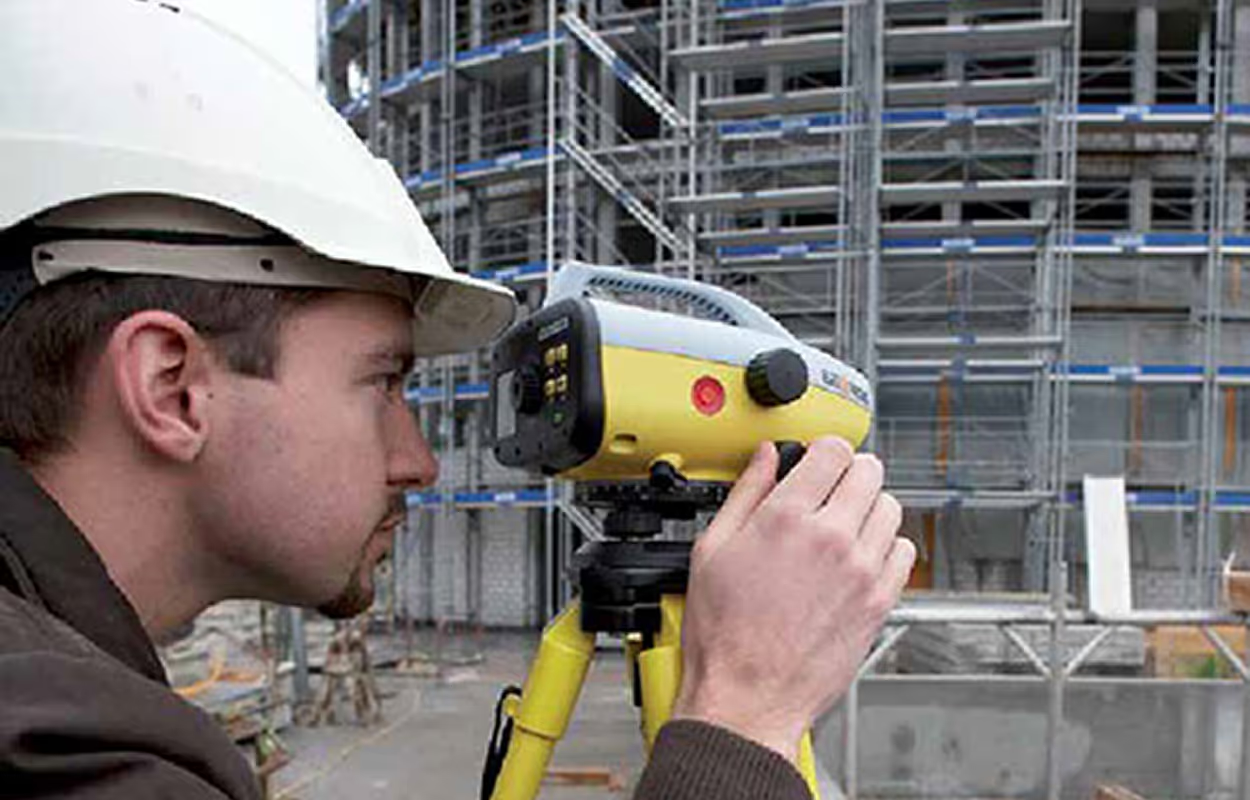
Field Capture Essentials
- Coverage and line of sight: Plan enough stations so that every wall, edge, and opening is visible from at least two viewpoints. Occluded areas force guesswork during feature extraction.
- Targets and control: Use spheres, checkerboards, or natural overlap for registration. Always verify residual error before exporting your files.
- Color and imagery quality: Colorized scans and clear panorama images make it easier to identify features like doors and windows.
- Logical naming: Name scans by floor, zone, or area. Consistent organization reduces confusion when working with subsets later.
E57 vs FLS File Formats
- E57: Open, vendor-neutral format supported by most point cloud and CAD applications. A safe choice when exporting scans from different hardware.
- FLS: Native to the FARO ecosystem and widely used in practice. Fully supported in scan to CAD workflows.
If your scanner outputs a proprietary format, convert it to E57 or FLS before you begin. Using a standard format ensures compatibility and avoids delays downstream.
Coordinate and Units Checklist
One of the most common causes of errors in scan to CAD projects is misaligned coordinates. Use this quick checklist before connecting to CAD:
- Confirm units (meters or feet) match your CAD template.
- Decide on an origin (local zero, site grid, or survey control).
- Check vertical datum (absolute heights or project relative).
- Record any site rotation if the grid does not align to CAD X.
Good preparation in the field and in file setup prevents the “where did my drawing go” problem and ensures smooth alignment once you begin drafting.
Setting Up Your CAD Template
Before starting the scan to CAD workflow, make sure your CAD environment is ready. A properly configured template ensures that extracted features land on the correct layers and that your drawings follow project standards without heavy cleanup later.
Why Templates Matter
When features are placed on the right layers and styled correctly from the start, you avoid hours of restyling, re-layering, or block replacement at the end of the project. This keeps your workflow consistent and your deliverables client-ready.
CAD Template Checklist
- Layers: Create dedicated layers for walls, doors, utilities, topo points, and text.
- Blocks: Load standard blocks such as door symbols, pipe tags, and elevation marks.
- Text and dimensions: Configure text styles and dimension styles to match project units.
- Base sheet: Set up a base drawing if you plan to generate plan or section sheets.
By investing a few minutes in template setup, you lock in accuracy, consistency, and efficiency. Every extracted element from your scan will flow directly into a DWG that meets your office or client standards.
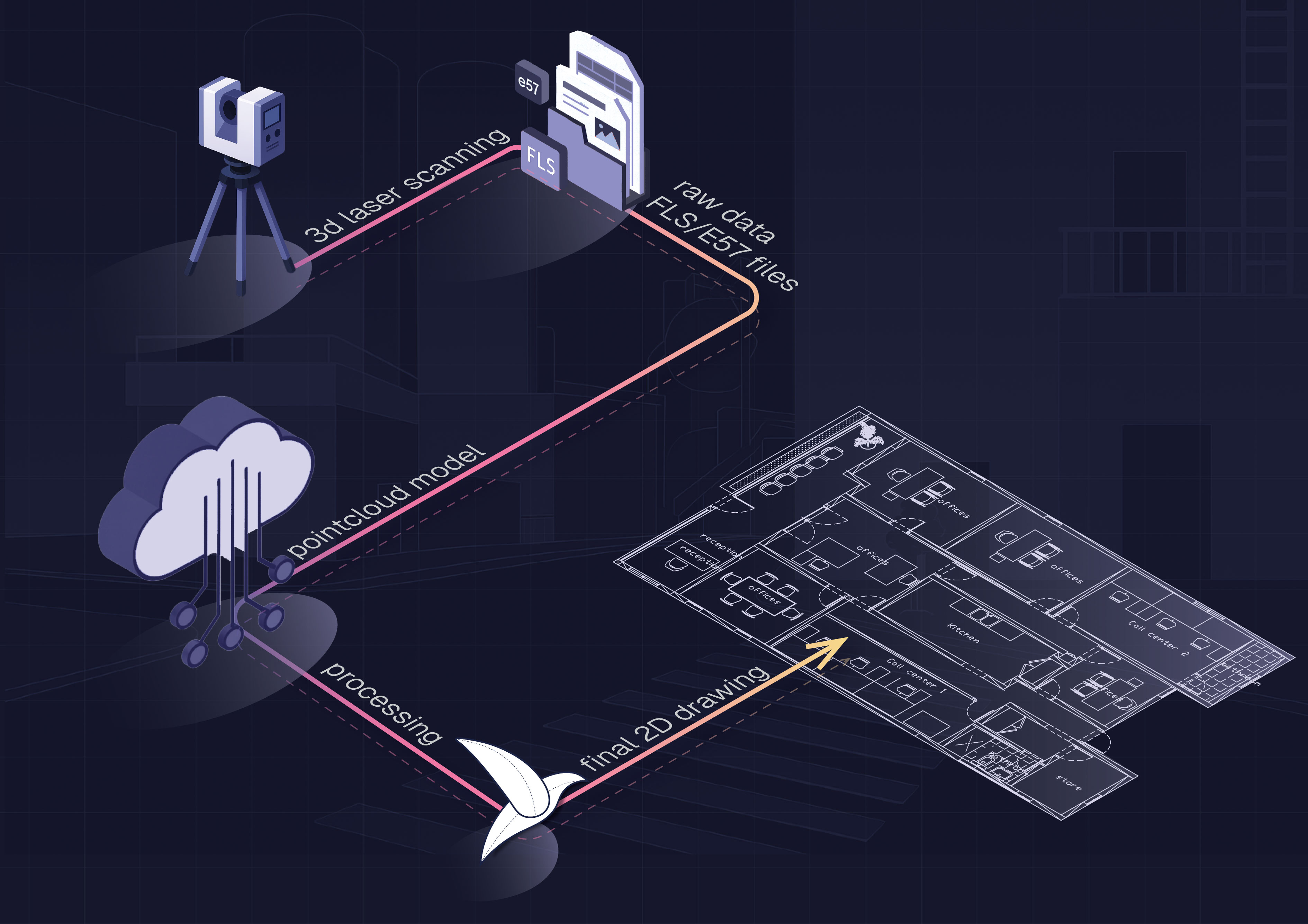
Automated 3 Step Scan to CAD Workflow
With automation built into Nest3D, the scan to CAD workflow is reduced to just three simple steps. This streamlined process lets you move from E57 or FLS scans to clean DWG drawings in minutes instead of hours.
Accuracy and Best Practices
A well prepared scan to CAD workflow delivers both speed and precision. By following a few best practices, you ensure that every drawing is accurate and consistent from project to project.
Proven Accuracy Habits
- Confirm units and coordinates so your CAD template and scan data are aligned from the start.
- Cross check spans by picking from more than one station when accuracy matters most.
- Zoom and verify critical details like corners and openings before extraction.
- Measure control points as a final QA step before issuing the DWG.
These habits, combined with automation, make the workflow both reliable and repeatable. Teams can move confidently from scan to CAD knowing that the output will meet professional standards every time.
Frequently Asked Questions About Scan to CAD Workflows
Conclusion: Mastering How Scan to CAD Works
Learning how scan to CAD works gives surveyors, architects, and contractors a repeatable process to turn raw scan data into usable CAD deliverables. By preparing your files, setting up a template, and following a structured workflow, you can produce accurate DWG drawings faster and with less effort.
Teams that adopt automated workflows report saving around 60 percent of drafting time compared to manual tracing. That means projects finish sooner, costs drop, and ROI is realized almost immediately.
If you are ready to see the difference for yourself, there is no reason to wait.
Turn Point Clouds into CAD in Seconds
Cut drafting time by 60 percent and deliver accurate DWG drawings without manual tracing. Try Nest3D free for 14 days with no credit card required.
Get Started for Free
.svg)


.svg)
