

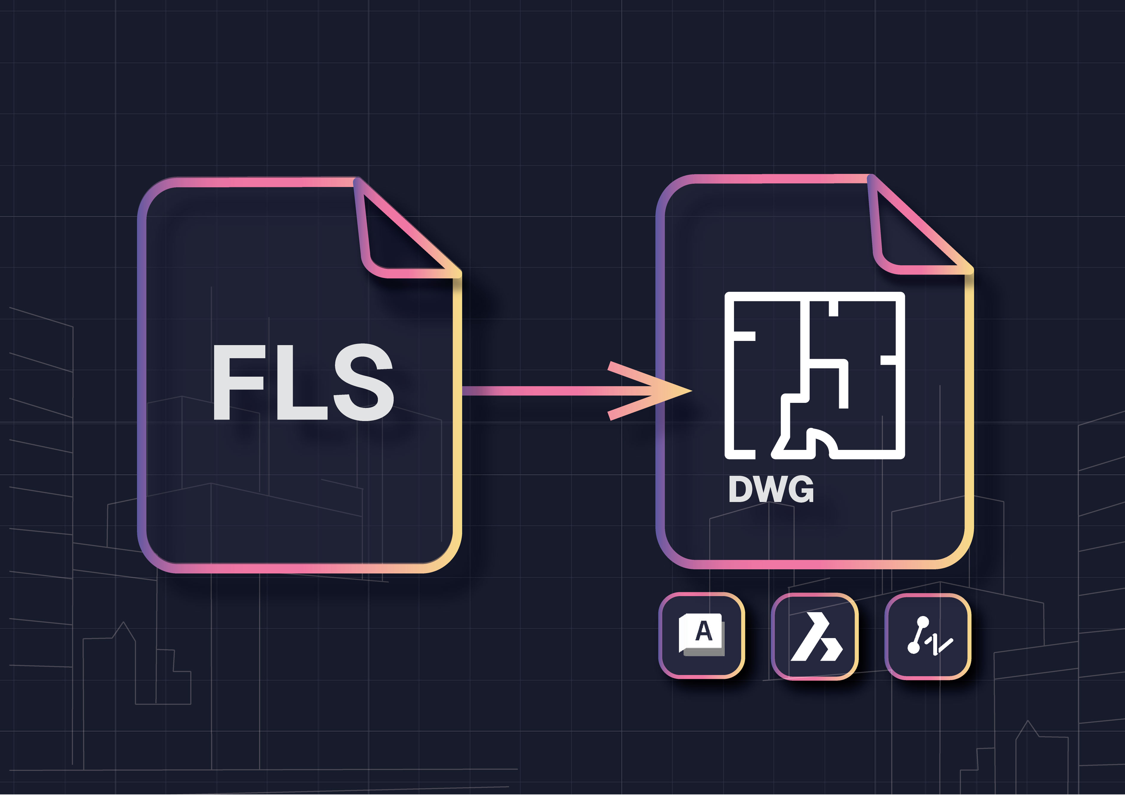
FLS is the native format of Faro Scene, one of the most widely used laser scanning platforms. While it captures detailed point clouds, clients rarely want FLS files because they are not practical deliverables. Architects, engineers, and contractors need clean CAD drawings in DWG format that they can edit and reuse across projects.
Manual FLS to DWG conversion is possible but often slow, error-prone, and costly. This article explains why FLS files matter, the challenges of converting them, and how automation makes it faster and more accurate to convert FLS point clouds to CAD inside AutoCAD, BricsCAD, or ZWCAD.
What Is an FLS File and Why It Needs Conversion
An FLS file is the native output of Faro laser scanners, managed through Faro Scene. It contains millions of 3D points that represent real-world surfaces with high accuracy. These datasets are ideal for storing scan information but are not suitable as deliverables on their own.
Most clients and project stakeholders require CAD drawings in DWG format, not raw point clouds. Converting Faro Scene to AutoCAD or other CAD platforms is essential because:
- DWG drawings are editable and can be updated as projects evolve
- Standardized templates ensure layers, linetypes, and blocks follow company or industry standards
- Compatibility with AutoCAD, BricsCAD, and ZWCAD makes collaboration easier
- Deliverables are lighter and easier to share compared to massive FLS point cloud files
In short, FLS to DWG conversion is the bridge between raw Faro scan data and usable CAD drawings that keep projects moving forward.
Challenges of Converting FLS Files to CAD Manually
Survey teams that try to handle FLS to DWG conversion manually often face major roadblocks. Faro Scene allows you to view and slice point clouds, but producing accurate CAD drawings still requires hours of tracing inside AutoCAD or other CAD tools.
Common challenges include:
- Slow workflows: slicing planes and redrawing walls or openings can take days
- Accuracy issues: manual tracing introduces errors when interpreting noisy scan data
- High labor costs: senior staff often handle the basics because juniors struggle with large FLS datasets
- Risk of rework: missed geometry or wrong elevations are discovered late, forcing revisions
- File bloat: exporting between Faro Scene and CAD platforms often breaks context and increases cleanup work
These issues make manual methods unsustainable for firms that want to stay competitive. That is why more teams are moving toward automated solutions for Faro point cloud to CAD conversion.
Automated FLS to DWG Conversion with Nest3D
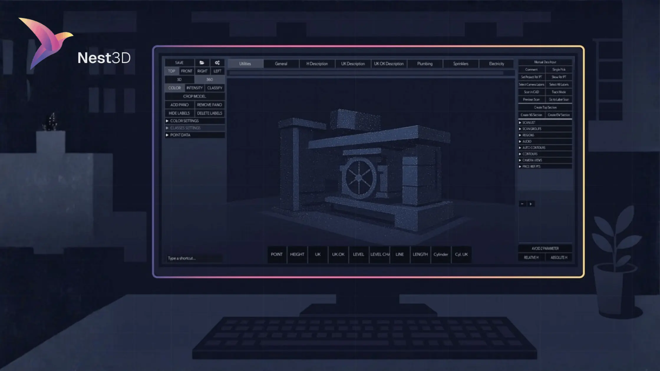
Modern automation makes it faster and easier to convert FLS point clouds to CAD without the frustration of manual tracing. Instead of slicing planes and redrawing geometry, Nest3D runs directly inside AutoCAD, BricsCAD, and ZWCAD to generate DWG deliverables in real time.
The process is simple:
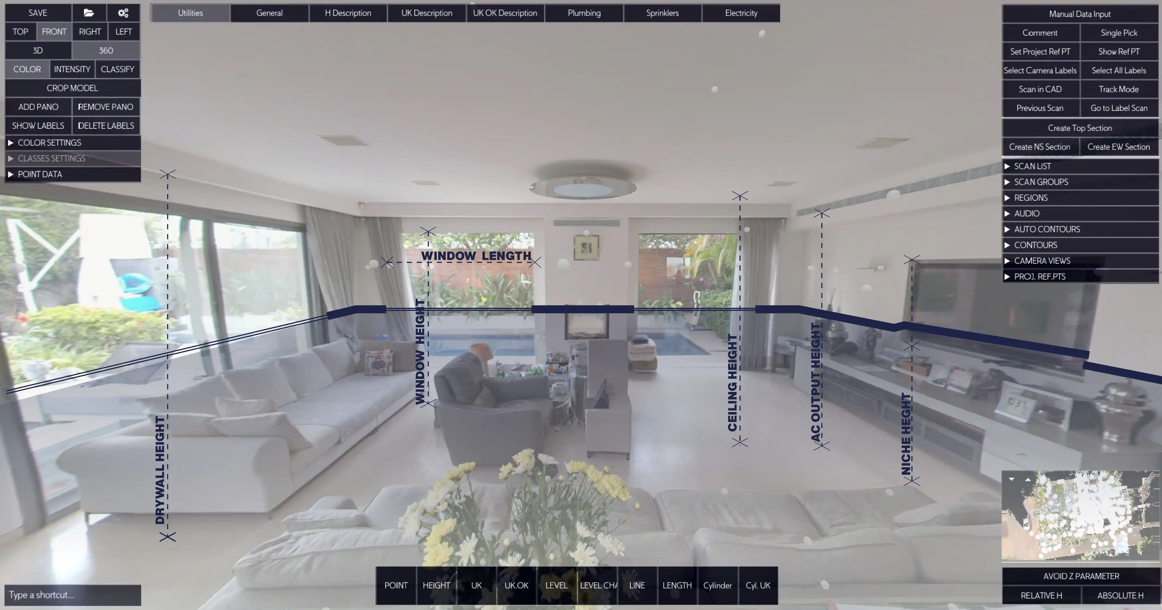
1. Load your FLS scan into Nest3D alongside your DWG template
2. Pick features in a 360° panorama such as walls, doors, and survey points
3. Watch clean linework appear instantly in CAD, mapped to your layers, linetypes, and blocks
This workflow eliminates hours of repetitive drafting while keeping your deliverables accurate and consistent. Teams using Nest3D for FLS to DWG conversion report up to 60 percent faster project turnaround compared to manual methods.
Benefits of Converting FLS Point Clouds to CAD with Automation
Switching from manual tracing to automated FLS to DWG conversion brings measurable advantages for surveyors and CAD teams.
- Significant time savings: projects are completed up to 60 percent faster
- Lower project costs: reduced need for outsourcing and senior staff time
- Consistent deliverables: every drawing follows your DWG template for layers, linetypes, and blocks
- Improved accuracy: linework is tied directly to FLS scan data, reducing errors from interpretation
- Scalable production: junior staff can handle extractions while senior staff focus on review and delivery
- Better collaboration: lightweight DWG outputs are easier to share than massive FLS files
By automating the process, survey firms not only speed up delivery but also improve reliability, ensuring clients receive professional CAD drawings that are ready to use immediately.
FLS to DWG Conversion in AutoCAD, BricsCAD, and ZWCAD
One of the biggest advantages of Nest3D is that it works inside the CAD platforms survey teams already use. Instead of exporting from Faro Scene and cleaning files later, you can handle FLS to DWG conversion directly in your preferred environment.
- AutoCAD: Generate DWG linework directly from FLS scans without leaving AutoCAD. Geometry follows your layers, linetypes, and blocks so the output is ready for delivery.
- BricsCAD: Stream linework from FLS point clouds into BricsCAD drawings. Nest3D applies your templates automatically to maintain drafting standards.
- ZWCAD: Use the same workflow inside ZWCAD for fast, accurate FLS to CAD conversion without complex imports or file conversions.
No matter which CAD platform you rely on, Nest3D eliminates the extra steps that slow projects down, producing clean DWG deliverables in real time.
Common Use Cases for FLS to DWG Conversion
Converting FLS files to DWG is essential across a wide range of surveying and engineering projects. The most common use cases include:
- As-built floor plans: create accurate drawings for renovations, tenant fit-outs, or facility updates
- Site plans and elevations: extract features directly from FLS scans to produce clean deliverables
- Topographic mapping: measure points in absolute mode for ground shots and site surveys
- Facility management: replace outdated or missing drawings with updated CAD files
- Multi-site projects: standardize extraction workflows so junior staff can handle production at scale
These use cases highlight why Faro point cloud to CAD conversion is becoming a standard requirement in professional surveying. Firms that adopt automation deliver faster and more accurate results across all project types.
Best FLS to DWG Workflow for Surveyors and CAD Teams
A smooth FLS to DWG workflow is about more than just software. It combines automation with clear standards and simple habits that keep projects efficient. Survey teams that succeed with FLS conversion typically follow these best practices:
- Start with a clean DWG template so every drawing follows your office standards for layers, linetypes, and blocks
- Segment large point clouds by floor or zone to keep performance fast in AutoCAD, BricsCAD, or ZWCAD
- Use panorama navigation for visual accuracy instead of relying only on slices
- Automate repetitive tasks with custom buttons for doors, tags, and symbols to cut down on cleanup work
- Run a quick QA check before delivery to confirm scale, orientation, and block placement
This approach ensures that automation delivers not just speed but also reliability. Instead of spending days redrawing in CAD, survey teams can focus on quality control and client delivery.
Frequently Asked Questions About FLS to DWG Conversion
Conclusion: Faster FLS to DWG Conversion Starts Here
Turning Faro Scene scans into DWG drawings does not need to be slow or complicated. Manual tracing wastes hours, and outsourcing adds cost without guaranteeing consistency. With Nest3D, you can load your FLS files directly into AutoCAD, BricsCAD, or ZWCAD, pick features in a 360° panorama, and watch clean linework appear instantly.
Survey teams using Nest3D report faster turnaround, lower project costs, and deliverables that always follow their CAD standards.
Turn Point Clouds into CAD in Seconds
Cut drafting time by 60 percent and deliver accurate DWG drawings without manual tracing. Try Nest3D free for 14 days with no credit card required.
Get Started for Free
.svg)


.svg)
