

Introduction: Why E57 to DWG Conversion Matters
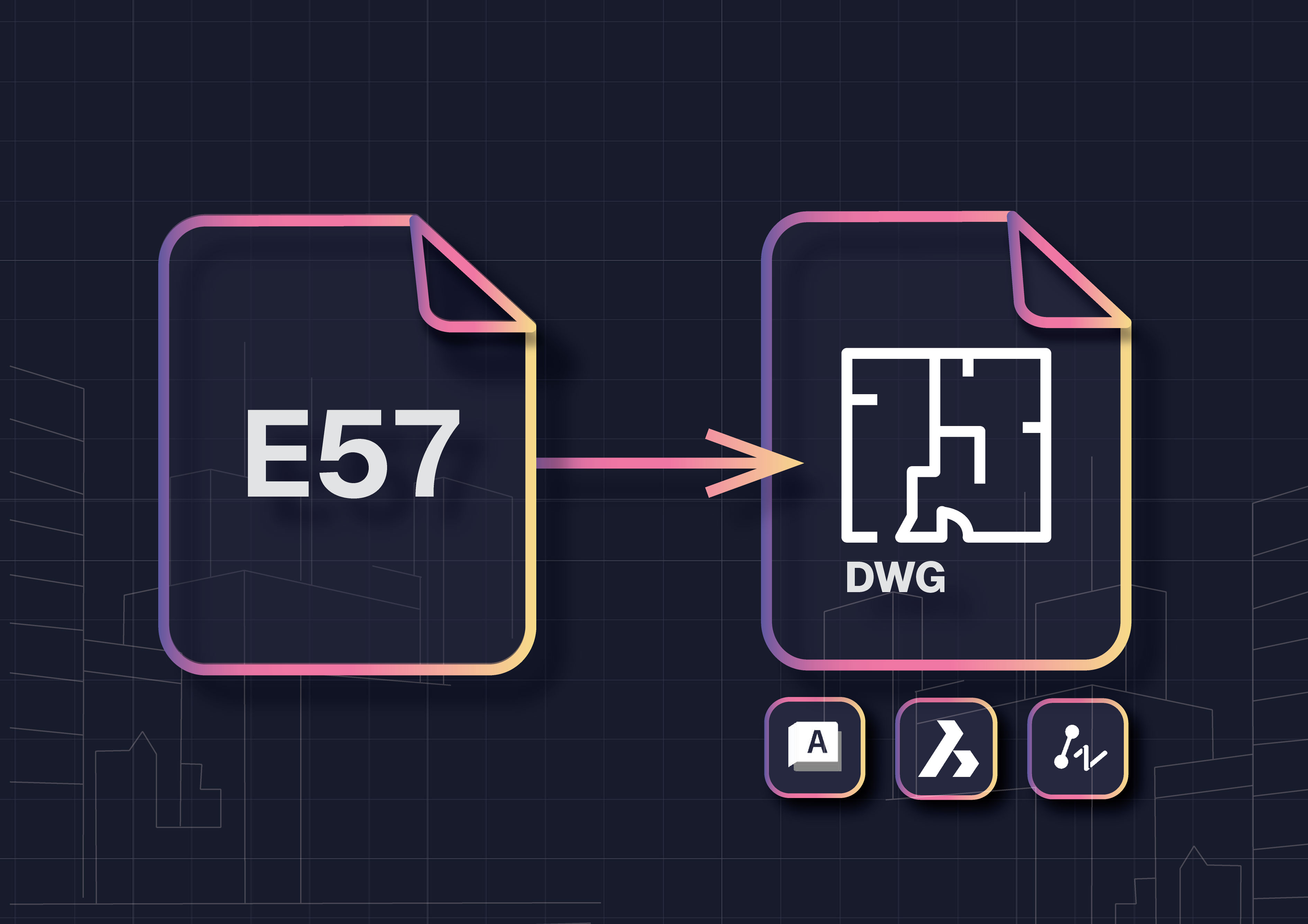
Converting E57 to DWG is one of the most common tasks for surveyors and CAD teams who work with laser scan data. An E57 file is excellent for storing millions of 3D points captured in the field, but it is not a deliverable your clients can use. Architects, engineers, and contractors almost always expect DWG drawings that are editable, lightweight, and aligned with project standards.
This is where point cloud to DWG conversion becomes critical. By turning raw E57 scans into CAD drawings, teams can produce accurate floor plans, elevations, and site plans that follow company templates for layers, linetypes, and blocks. Without this step, projects stall under heavy scan files, outsourcing costs rise, and deadlines slip.
Modern E57 to CAD workflows solve these problems by keeping the process inside AutoCAD, BricsCAD, or ZWCAD, avoiding file conversions and eliminating repetitive manual tracing. With the right software, survey teams consistently report cutting drafting time by up to 60 percent while delivering higher-quality results.
What Is an E57 File?
An E57 file is a vendor neutral point cloud format designed to store large amounts of 3D scan data. It contains millions of points with attributes like position, color, and intensity, making it one of the most common formats produced by terrestrial laser scanners and registration software.
While E57 files preserve the full quality of a scan, they are not usable deliverables for most projects. Architects, engineers, and contractors typically require DWG drawings that are clear, editable, and compatible with industry standard CAD platforms. That is why E57 to DWG conversion is such an essential step in the workflow. It bridges raw scan data with practical, project ready outputs.
Why Convert E57 to DWG?
Converting E57 point clouds to DWG drawings is essential for surveyors, architects, and CAD teams that need usable deliverables instead of raw scan data. An E57 file captures reality in millions of points, but those points alone cannot be edited, plotted, or shared effectively with clients.
With a proper E57 to DWG workflow, you can:
- Produce accurate as-built floor plans, elevations, or site plans
- Keep projects consistent by applying your DWG template standards for layers, linetypes, blocks, and text styles
- Replace slow manual slice-and-trace methods with panorama picking that writes linework directly into CAD
- Scale production by letting junior staff handle drafting while senior staff perform quick reviews
- Deliver files that open instantly in AutoCAD, BricsCAD, or ZWCAD without additional conversions
By turning scan data into clean DWG drawings, teams save significant time, reduce outsourcing costs, and ensure every project follows consistent CAD standards.
E57 to DWG in 3 Simple Steps
Step 1. Load your E57 and DWG template in CAD
Open your DWG template in AutoCAD, BricsCAD, or ZWCAD. Attach the E57 point cloud and confirm units. If needed, set relative or absolute heights so your slice aligns with the deliverable.
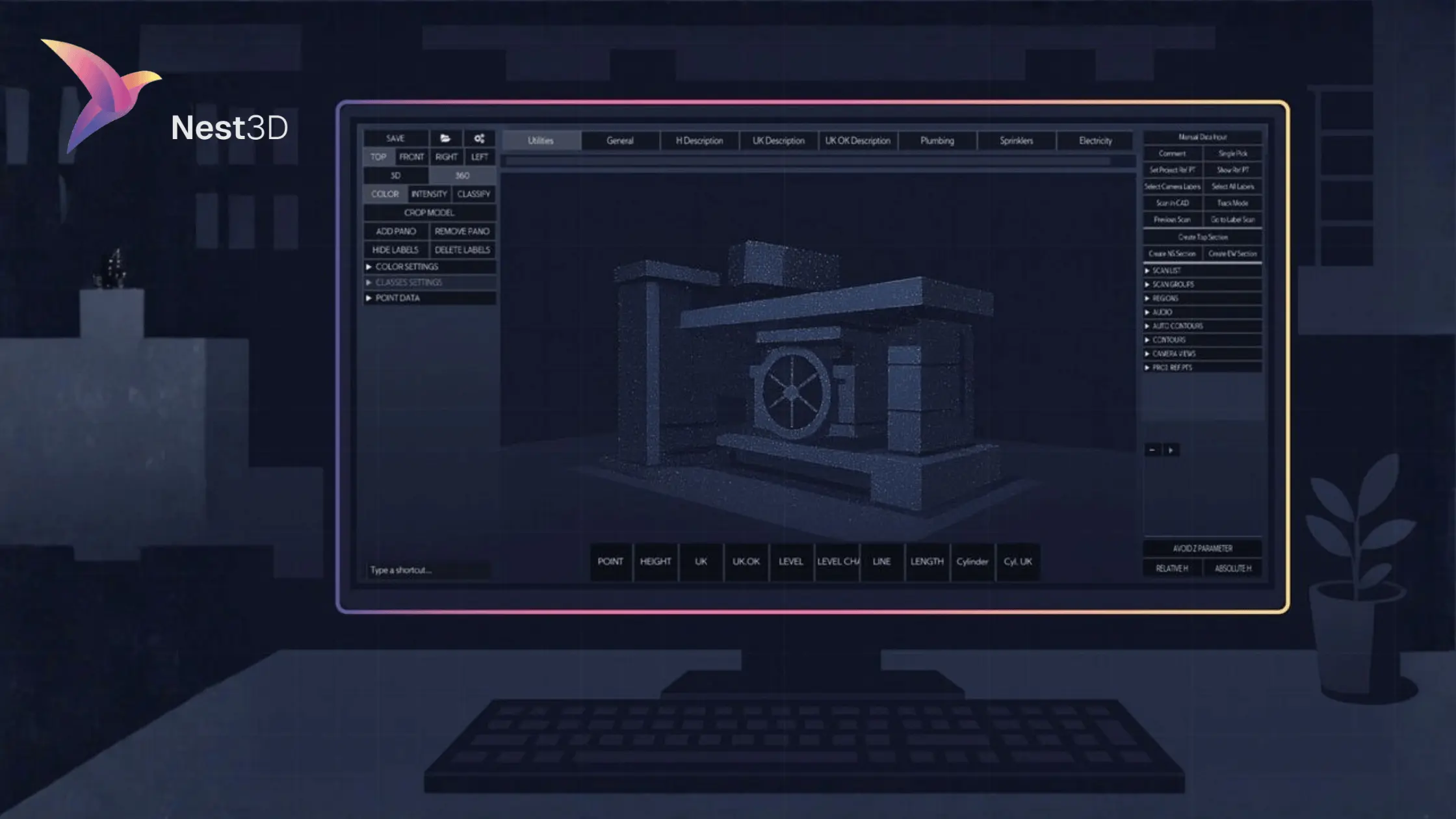
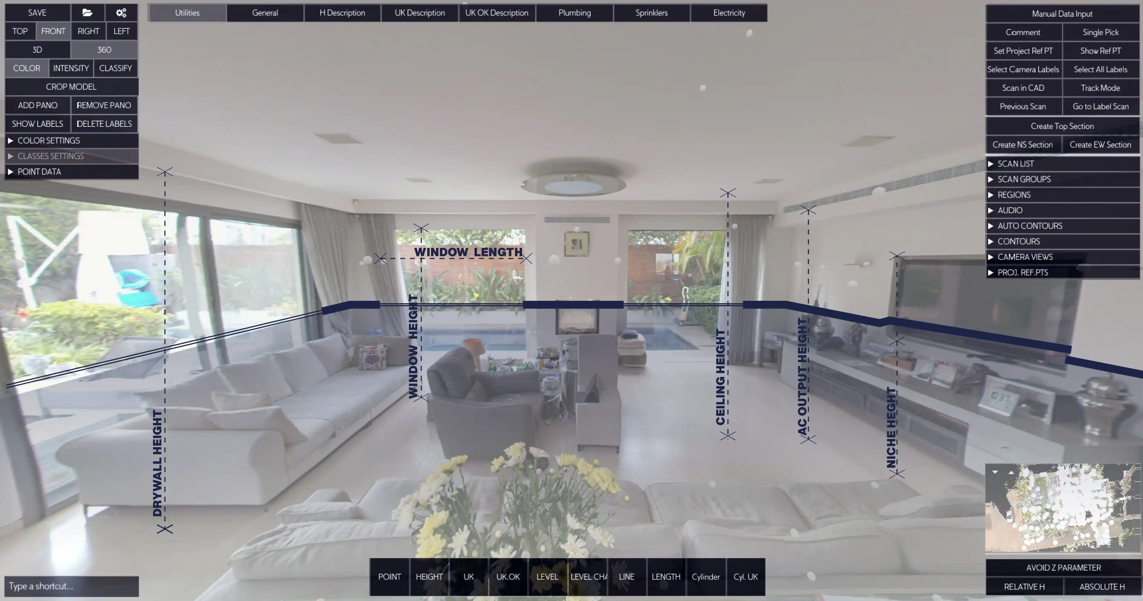
Step 2. Pick features in the 360 panorama
Navigate the panorama and click features like walls, doors, openings, survey points, cylinders, and levels. Use your custom buttons to drop blocks and text that match your CAD standard. Linework is measured from the point cloud for accuracy.
Step 3. See the DWG update live
Geometry streams directly into your drawing on the correct layers, linetypes, and blocks. Save the file, run a quick QA, and you have a clean E57 to DWG output ready to share.
Why E57 to DWG Is Easier with Nest3D
Converting E57 files to DWG is often described as complex, but with the right software the process is straightforward and reliable. Nest3D removes the bottlenecks that usually slow survey teams down:
- No heavy exports – linework is generated directly inside CAD, so you skip extra file shuffling.
- Consistent accuracy – geometry is picked visually from the panorama and lands on the right layers.
- Smaller file sizes – lightweight data handling keeps your CAD projects responsive.
- Template compliance – drawings follow your own DWG standards, reducing cleanup.
- Fast QA – a quick review confirms units, orientation, and layers before delivery.
The result is a workflow that feels natural inside AutoCAD, BricsCAD, or ZWCAD, producing clean DWG deliverables with less effort.
FAQs About E57 to DWG Conversion
Conclusion: E57 to DWG Conversion Made Simple
Converting an E57 point cloud to a DWG drawing does not need to be slow or complex. With the right software, surveyors and CAD teams can transform raw scan data into accurate floor plans, elevations, or site drawings in minutes instead of hours.
Tools like Nest3D streamline the process by letting you work directly inside AutoCAD, BricsCAD, or ZWCAD. Linework follows your templates, accuracy is preserved, and teams consistently report up to 60 percent faster drafting compared with manual tracing.
If your projects rely on E57 scans, upgrading to an automated workflow is one of the easiest ways to save time, cut costs, and deliver higher-quality results.

Turn Point Clouds into CAD in Seconds
Cut drafting time by 60 percent and deliver accurate DWG drawings without manual tracing. Try Nest3D free for 14 days with no credit card required.
Get Started for Free
.svg)


.svg)
